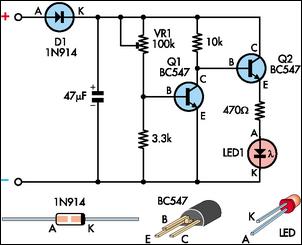
Is it nice? We can notice it easily.įirst, see you see 4 transistors and components more than 2 circuits above. We connect this circuit to indicate the status of the battery. # 3: LED battery status indicator circuit using 4 Transistors So, LED1 show up to alert us the battery nearly run out. The transistor Q1 will stop conducting the current. Makes LED1 go out.īut in contrast, the battery voltage is lower than 4.8V. But makes a Q2 transistor does not work.īecause no current to base of Q2. When this circuit measures the voltage level of the full Ni-HM battery.Ī current flows through R1 and R2 to bias a base of Q1. Or it indicated that the battery is running out. We use this circuit for indicating a voltage level of Ni-HM or Ni-cad battery. You can try to change any resistors as the input voltage. But the current can flow to the bias base of Q2. In contrast, the battery is lower voltage down. The Q1 runs, because getting a current bias. A current flows through 18K and VR1 to the base of Q1. Imagine you use this circuit to a 6V battery. They use a few electronics parts also just transistor BC547 and others.

When the battery voltage reduces down to a set point. we can adjust VR1 to set a level of checking voltage. It can apply to an input voltage of 3V to 15V. The first circuit is the simplest battery indicator circuit.
LOW BATTERY INDICATOR CIRCUIT DIAGRAM UPDATE
GET UPDATE VIA EMAIL # 1: Simple Battery Low Voltage Alarm Indicator


 0 kommentar(er)
